
 Tiếng Việt


Description
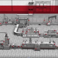
Smart Machine Safety is about enabling the equipment, machinery, and devices in a manufacturing plant and industrial operations to be connected and can provide real time information as well as be controlled via intelligent software.
“Safety as a core system function”
- Global Compliance – Global Machines
- Reduced Costs & Common Designs
- Increased Productivity
- Reduced Floor Space and Direct Labor
- Improved Ergonomics
- Reduced Injuries
How SMART assets evolve safety
Predictive maintenace:
Operations of safety devices per shifts are captured
Monitoring number of operations helps predict when device is at end of life
Information is available for maintenance staff to replace device
Device can be replaced at next planned maintenance schedule
Machine uptime from Smart Safety data
Machine operator opens interlocked guard door to fix tape. Device operation is logged in system
Production manager has all data available on safety device actions
Production manager and machine operator discuss reason of frequent access. Tape causing problem can be replaced
Machine running more efficiently with less maintenance required
How to build Smart Machine Safety?
- New tools: Emergence of Global Standards – ISO, IEC, Standard Machine Designs that are Globally Compliant
- New Safety Technologies – Tools for Improved
- Machine Performance
- New Design approaches – Passive, Configurable and Lockable
Functional Safety Lifecycle

Step 1: Risk Assessment – The Foundation
Provides Safety Performance Level – Design Target
Creates the Foundation of the Safety System Functional
Requirements, System Design and Validation Protocol
Shows “Due Diligence” and Global Compliance (Ref. ISO 12100)

Step 2: Safety Function Definition
Safety Functions are a combination of input, logic and output devices

Step 3: Safety Functions: Characteristics & Block Diagram
Typical safety function diagram

- The machine designer shall select an architecture – circuit structureCat B, 1, 2, 3 or 4
- Determine MTTFd for the Channel
- Calculate Diagnostic Coverage (DC)
- Evaluate Common Cause Failure Protection
- Determine Performance Level – PLr =< PL? This is Verification
Step 4: SAFETY SYSTEM INSTALLATION & VALIDATION
Verification and Validation plans include:
- Installation & Wiring Verification
- Operational Verification & Validation
- Network Verification & Validation
- Controller Verification & Validation
Includes:
Functional Testing & FaultInjectionTesting
Step 5: Maintain & Improve
There should be documented systems in place for change management/modification


There are no reviews yet.